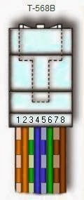
RJ-45 connector data cable contains 4
pairs of wires each consists of a solid colored wire and a strip of the same
color. There are two wiring standards for RJ-45 wiring: T-568A and T-568B.
Although there are 4 pairs of wires, 10BaseT/100BaseT Ethernet uses only 2
pairs: Orange and Green. The other two colors (blue and brown) may be used for a second
Ethernet line or for phone connections.
.
|
|
To create a straight-through cable,
you'll have to use either T-568A or T-568B on
both ends of the cable. The diagram depicted on the left and right shows clip
of the RJ-45 connector down.
To create a cross-over cable,
you'll wire T-568A on one end and T-568B on
the other end of the cable.
The straight-through
cables are used when connecting Data Terminating Equipment (DTE) to Data
Communications Equipment (DCE), such as computers and routers to modems
(gateways) or hubs (Ethernet Switches). The cross-over cables are used when
connecting DTE to DTE, or DCE to DCE equipment; such as computer to computer,
computer to router; or gateway to hub connections. The DTE equipment
terminates the signal, while DCE equipment do not.
|
|
|
More on straight-through and cross-over connections
The RJ45 data
cables we use to connect computers to a Ethernet switch is straight-through
cables. As noted above, the RJ45 cable uses only 2-pairs of wires: Orange (pins 1 & 2) and Green (pins 3 & 6). Pins 4, 5 (Blue) and 7, 8 (Brown)
are NOT used. Straight-through cable, as its name suggests, connects pin 1
to pin 1, pin 2 to pin 2, pin 3 to pin 3, and pin 6 to pin 6. Cross-over
cables are used to connect TX+ to RX+, and TX- to RX-, which connects pin 1
to pin 3, pin 2 to pin 6, pin 3 to pin 1 and pin 6 to pin 2. The unused
pins are generally connected straight-through in both straight-through and
cross-over cables.
To network two
computers without a hub, a cross-over cable is used. Cross-over cable is
also used to connect a router to a computer, or ethernet switch (hub) to
another ethernet switch without an uplink. Most ethernet switches today provide
an uplink port, which prevents a use of cross-over cable to daisy chain
another ethernet switch. Straight-through cables are used to connect a
computer to an ethernet switch, or a router to an ethernet switch.
Pin Number
Designations
There are pin number
designations for each color in T-568B and T-568A.
T-568B T-568A
--------------------------
------------------------
Pin
Color Pin
Name Color Pin Name
---
-------------
--------
------------- --------
1
Orange Stripe Tx+ Green Stripe Rx+
2
Orange Tx- Green Rx-
3
Green Stripe Rx+ Orange Stripe Tx+
4
Blue Not Used Blue Not Used
5
Blue Stripe Not
Used Blue Stripe Not Used
6
Green Rx- Orange Tx-
7
Brown Stripe Not
Used Brown Stripe Not Used
8
Brown Not
Used Brown Not Used
|
|
|
|
|
RJ45
Color-Coded Scheme
RJ45 cables have 8
color-coded wires, and the plugs have 8 pins and conductors. Eight wires
are used as 4 pairs, each representing positive and negative polarity. The
most commonly used wiring standard for 100baseT is T-586B stanrard
described above. Prior to EIA 568A and 568B standards, the color-coded
scheme was used to wire RJ45 cables. The table below depicts pin and color
schemes used in traditional and standardized setup.
|
|
Pin
|
Colored Scheme
|
T-568B (Common)
|
T-568A
|
|
|
1
|
Blue
|
Orange Stripe
|
Green Stripe
|
|
|
2
|
Orange
|
Orange
|
Green
|
|
|
3
|
Black
|
Green Stripe
|
Orange Stripe
|
|
|
4
|
Red
|
Blue
|
Blue
|
|
|
5
|
Green
|
Blue Stripe
|
Blue Stripe
|
|
|
6
|
Yellow
|
Green
|
Orange
|
|
|
7
|
Brown
|
Brown Stripe
|
Brown Stripe
|
|
|
8
|
White (or Grey)
|
Brown
|
Brown
|
|
|
|
|
|
|
RJ-45 Wiring
FAQ
1. What are T-568A and T-568B
wiring standards, and how are they different?
T-568A and T-568B
are the two wiring standards for RJ-45 connector data cable specified by
TIA/EIA-568-A wiring standards document. The difference between the two is
the position of the orange and green wire pairs. It is preferable to wire
to T-568B standards if there is no pre-existing pattern used within a
building.
2. What is RJ stands for?
RJ stands
for Registered Jacks. These are used in telephone
and data jack wiring registered with FCC. RJ-11 is a 6-position,
4-conductor jack used in telephone wiring, and RJ-45 is a 8-position,
8-conductor jack used in 10BaseT and 100BaseT ethernet wiring.
3. What is the
Category Rating System?
Electronic
Industries Association (EIA) developed the TIA/EIA-568-A standard, which
specifies wiring and performance standards for Unshielded Twisted Pair
(UTP) cabling. Category Rating System specifies the definition of
performance categories for 100 ohm UTP cabling system.
Category 3 specifies the twisted pair cable and
connecting hardware that can support transmission frequency up to 16MHz,
and data rates up to 10Mbps. This is primarily used in telephone wiring.
Category 4 specifies cables and connectors that
supports up to 20MHz and data rates up to 16Mbps. With introduction of
category 5, this is a rarely used category.
Category 5 specifies cables and connectors that
supports up to 100MHz and data rates up to 100Mbps. With 100BaseT Ethernet
today, Category 5 is a widely used cabling system that matches todays
high-speed data requirements.
|
|
Category
|
TIA/EIA Standard
|
Description
|
|
|
Cat 1
|
None
|
POTS, ISDN and
doorbell wiring
|
|
|
Cat 2
|
None
|
4 Mbps token
ring networks
|
|
|
Cat 3
|
TIA/EIA 568-B
|
10 Mbps Ethernet
- frequency up to 16MHz
|
|
|
Cat 4
|
None
|
16 Mbps token ring
networks - frequency up to 20MHz
|
|
|
Cat 5
|
None
|
100 Mbps
Ethernet - frequency up to 100 MHz
Not suitable for GigE (1000BaseT)
|
|
|
Cat 5e
|
TIA/EIA 568-B
|
100 Mbps &
GigE Ethernet - frequency up to 100 MHz
|
|
|
Cat 6
|
TIA/EIA 568-B
|
2x Performance
of Cat 5 & 5e - frequency up to 250 MHz
|
|
|
Cat 6a
|
None
|
Future
specification for 10Gbps application
|
|
|
Cat 7
|
ISO/IEC 11801
Class F
|
Designed for
transmission at frequencies up to 600 MHz
|
|
4. What is UTP Cable?
UTP stands
for Unshielded Twisted Pair. It is the
cabling system with one or more pairs of twisted insulated copper wires
contained in a single sheath. It is the most widely used cabling system in
telecommunications and data communications environment today.
|
|


ReplyDeletenice blog..
Best wireless router